Embark on an enlightening journey with Blueprints Level 3 Lesson 1, where architectural drawings come to life. This comprehensive guide unveils the intricacies of blueprints, empowering you with the knowledge and skills to navigate construction projects with confidence.
Delve into the fundamentals of architectural drawing, decipher the language of blueprints, and explore the practical applications that drive successful construction endeavors.
Lesson Overview
Lesson 1 of Blueprints Level 3 provides a comprehensive introduction to the concept of blueprints. It establishes a solid foundation for understanding the purpose, components, and significance of blueprints in the field of construction.
The lesson covers key learning objectives, including:
- Understanding the role and importance of blueprints in construction.
- Identifying the different types of blueprints and their uses.
- Interpreting and understanding the symbols and conventions used in blueprints.
- Developing a foundational knowledge of blueprint reading and understanding.
Architectural Drawing Fundamentals

Architectural drawing is the graphical representation of buildings and structures, providing a clear and concise representation of the design intent. It involves the use of specific line types, symbols, and scales to convey information about the size, shape, and layout of a building.Precision
and accuracy are paramount in architectural drawings, as they serve as the basis for construction and renovation projects. They enable architects and engineers to communicate their design ideas effectively and ensure that the building is constructed as intended.
Line Types
Architectural drawings utilize various line types to represent different elements of a building:
- Visible lines: Solid lines that depict visible edges of the building.
- Hidden lines: Dashed lines that represent edges that are not visible in the drawing.
- Center lines: Thin, alternating long and short dashes that indicate the center of a feature.
- Dimension lines: Arrows with lines connecting them that provide measurements.
Symbols
Architectural drawings also employ symbols to represent common building components, such as:
- Doors: Rectangles with a line representing the swing direction.
- Windows: Rectangles with a cross inside.
- Stairs: A series of parallel lines with arrows indicating the direction of travel.
- Elevators: Rectangles with a diagonal line inside.
Scales
Scales are used in architectural drawings to reduce the size of the building to a manageable scale for drawing purposes. They are expressed as a ratio, such as 1:100, indicating that one unit on the drawing represents 100 units in real life.Different
types of architectural drawings include:
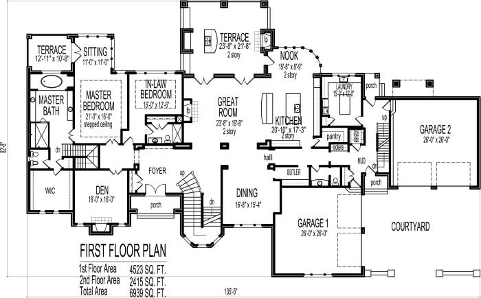
- Floor plans: Overhead views of a building showing the layout of rooms, walls, and openings.
- Elevations: Vertical views of a building’s exterior or interior, showing the height and proportions.
- Sections: Cut-away views of a building showing the interior construction and materials.
Introduction to Blueprints

Blueprints are detailed technical drawings that provide a comprehensive guide for constructing a building or structure. They serve as a visual representation of the design, specifying the dimensions, materials, and construction methods.
Blueprints are indispensable for construction professionals, enabling them to visualize the project, plan the construction process, and ensure the project is built according to the architect’s specifications.
Types of Blueprints
There are various types of blueprints, each serving a specific purpose in the construction process:
- Architectural Blueprints:Illustrate the overall design and layout of the building, including floor plans, elevations, and sections.
- Structural Blueprints:Provide detailed information about the building’s structural elements, such as foundations, beams, and columns.
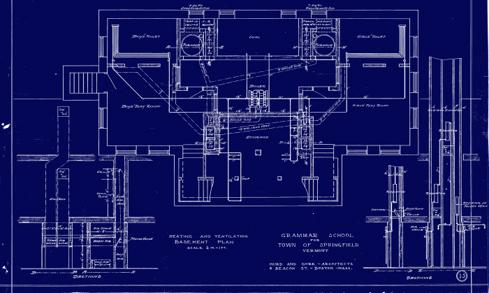
- Mechanical Blueprints:Specify the design and installation of mechanical systems, including heating, ventilation, and air conditioning.
- Electrical Blueprints:Detail the electrical systems, including wiring, outlets, and lighting.
Importance of Understanding Blueprints
Understanding blueprints is crucial for construction professionals to ensure accurate and efficient construction:
- Communication:Blueprints facilitate clear communication between architects, engineers, contractors, and other professionals involved in the construction process.
- Planning:They enable construction professionals to plan the sequence of construction activities, estimate materials, and determine labor requirements.
- Compliance:Blueprints ensure that the construction adheres to building codes and regulations, preventing costly errors and potential safety hazards.
- Problem-Solving:They provide a visual reference for identifying and resolving construction issues during the construction process.
Reading and Interpreting Blueprints
Blueprints are technical drawings that provide detailed instructions for constructing or renovating a building. Reading and interpreting blueprints is essential for architects, engineers, contractors, and anyone involved in the construction process.
Blueprints Level 3 Lesson 1 provides a solid foundation for understanding the basics of blueprints. To enhance your knowledge, don’t miss the periop 101 final exam 2023 . After reviewing this comprehensive exam, return to Blueprints Level 3 Lesson 1 to reinforce your understanding and prepare for future success in the field.
Blueprints contain a wealth of information, including dimensions, notes, symbols, and details. Understanding these elements is crucial for accurate interpretation and execution of the project.
Dimensions
Dimensions are measurements that indicate the size and location of building components. They are typically expressed in feet, inches, or millimeters and can be found in various places on the blueprint, such as on walls, windows, and doors.
Notes
Notes are written instructions or annotations that provide additional information about the project. They can include specifications for materials, construction methods, or any other relevant details.
Symbols
Symbols are graphical representations of building elements and components. They are used to convey complex information in a concise and standardized manner. Common symbols include:
- Lines: Indicate walls, doors, and windows.
- Circles: Represent plumbing fixtures, such as sinks and toilets.
- Squares: Indicate electrical outlets and switches.
- Triangles: Represent stairs and ramps.
Abbreviations
Abbreviations are used to save space and simplify communication. Some common abbreviations include:
- B.C. – Before Christ
- C.E. – Common Era
- ft – Feet
- in – Inches
- mm – Millimeters
Blueprint Design and Creation
The process of designing and creating blueprints involves translating architectural concepts into technical drawings that guide the construction process. It requires a combination of creativity, technical knowledge, and precision.
Computer-aided design (CAD) software has revolutionized blueprint creation. CAD software allows architects and designers to create digital models of buildings, which can then be used to generate precise and detailed blueprints. These models can be easily modified and shared, streamlining the design and collaboration process.
Types of CAD Software for Blueprint Design
- AutoCAD: A widely used industry-standard CAD software known for its versatility and powerful drafting tools.
- Revit: A BIM (Building Information Modeling) software that enables the creation of 3D models and generates coordinated blueprints.
- SketchUp: A user-friendly CAD software suitable for beginners and hobbyists, offering intuitive modeling capabilities.
- Vectorworks: A specialized CAD software for architects, providing advanced tools for architectural design and documentation.
- Archicad: A BIM software designed specifically for architects, featuring integrated tools for design, documentation, and project management.
Blueprint Revision and Management
Revisions and updates are inevitable in the blueprint development process. A systematic approach is crucial to manage these changes effectively, ensuring the accuracy and consistency of blueprints.
Importance of Version Control and Change Management
Version control systems track changes made to blueprints, allowing for easy restoration of previous versions if needed. Change management processes define procedures for reviewing, approving, and implementing changes, ensuring that revisions are controlled and authorized.
Tools and Techniques for Blueprint Revision and Management
Various tools and techniques facilitate efficient blueprint revision and management:
- Version Control Software:Tools like Git and SVN allow multiple users to collaborate on blueprints, track changes, and revert to previous versions.
- Change Request Systems:These systems provide a structured process for submitting, reviewing, and approving change requests, ensuring controlled implementation.
- Blueprint Revision Logs:Detailed logs document all revisions made to blueprints, including the date, author, and description of changes.
- Cloud-Based Collaboration Platforms:These platforms enable real-time collaboration on blueprints, allowing multiple users to make changes simultaneously.
Blueprint Applications in Construction: Blueprints Level 3 Lesson 1
Blueprints are indispensable tools in the construction industry, serving as detailed roadmaps that guide every aspect of the building process. They provide contractors and tradespeople with the precise instructions necessary to execute construction activities accurately and efficiently.
Blueprints are used throughout the construction timeline, from planning and design to the actual construction and completion of the project. They play a crucial role in:
Framing
Framing blueprints provide detailed instructions for constructing the structural framework of the building, including the placement of walls, beams, and trusses. These blueprints ensure that the structure is sound and meets building codes.
Plumbing, Blueprints level 3 lesson 1
Plumbing blueprints Artikel the design and installation of the water supply, drainage, and waste disposal systems. They indicate the location of pipes, fixtures, and appliances, ensuring that the plumbing system functions efficiently and complies with regulations.
Electrical Work
Electrical blueprints specify the placement of electrical outlets, switches, and wiring throughout the building. They ensure that the electrical system is safe, meets code requirements, and supports the building’s electrical needs.
Problem Solving and Accuracy
Blueprints are invaluable for solving construction problems and ensuring project accuracy. By studying the blueprints, contractors can anticipate potential issues and develop solutions before they arise. Additionally, blueprints serve as a reference point for resolving discrepancies and ensuring that the final product aligns with the original design intent.
Top FAQs
What is the significance of blueprints in construction?
Blueprints serve as the roadmap for construction projects, providing detailed instructions and specifications that guide every aspect of the building process.
How do I interpret the symbols and abbreviations used in blueprints?
Blueprints utilize a standardized set of symbols and abbreviations to convey information concisely. Refer to industry guides or consult with experienced professionals for clarification.
What is the role of computer-aided design (CAD) in blueprint creation?
CAD software revolutionizes blueprint creation, allowing architects and engineers to design and modify blueprints digitally, enhancing accuracy and efficiency.